

Last Updated: November 1, 2026
Quick Summary
Track wiring is the process of delivering power from a controller to the rails so locomotives can draw current and move. Good track wiring uses bus wires, feeders soldered beneath the rails, and tested connections placed before the track is laid.
- Plan the wiring and choose DC or DCC before laying any track.
- Solder feeders to the underside of a rail joiner or solder point, not the rail head.
- Space feeders every few feet on longer straight runs to limit voltage drop.
- Use an auto-reversing module or double-pole, double-throw switch on reversing loops.
- Test each block with a multimeter before powering the layout.
Table of Contents
- Why Track Wiring Matters Before You Lay a Single Rail
- Essential Tools and Materials for Track Wiring
- Model Train Track Feeder Wires: Placement and Spacing
- Model Train Wiring for DC: Step-by-Step Setup
- Model Train Wiring for DCC: What Changes and What Stays the Same
- Model Train Reversing Loop Wiring Without Short Circuits
- Common Track Wiring Mistakes and How to Troubleshoot Them
- Your First Wiring Project and Where to Get Supplies from BYMRR
- Frequently Asked Questions
Why Track Wiring Matters Before You Lay a Single Rail
Model train track wiring for beginners is the foundation of every working layout. Layouts where locomotives sit dead on the rails are very often a wiring problem rather than an engine problem. A model train track is a conductor, but only if the power reaches every section evenly and the connections stay solid.
Model train track wiring is the process of delivering power from a controller to the rails so locomotives can draw current and move.
Plan the wiring before you lay track. Sketch your layout, mark every section that needs its own power connection, and decide whether you will run DC or DCC. Changing that decision after the roadbed is down means pulling up track, which is far harder than doing it right the first time.
Essential Tools and Materials for Track Wiring
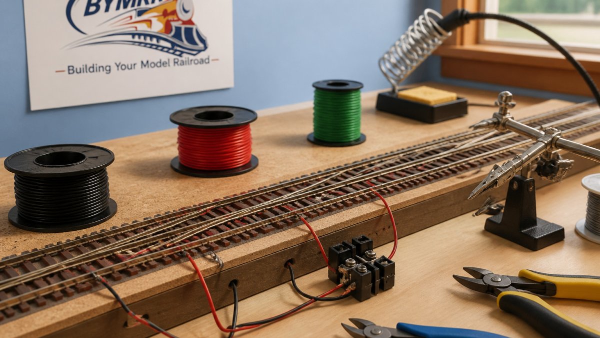
You do not need an expensive workshop to wire a layout, but a few tools make the job far easier. A soldering iron with a fine tip, rosin-core solder, wire strippers, a multimeter for checking continuity, and a supply of 22-gauge or 18-gauge feeder wire cover most beginner projects. For a broader look at the tools across model building, see the complete guide to essential tools. Track clips or rail joiners and a small box of terminal blocks help keep connections organized.
A common mistake is buying cheap tools that heat unevenly. A reliable iron that holds temperature will produce cleaner joints on brass and nickel-silver rail. Keep a multimeter on hand from the start, since it is the fastest way to confirm a connection before you power the layout.
For a full overview of tools beyond wiring, see our guide to model building tools.
Model Train Track Feeder Wires: Placement and Spacing
Feeder wires carry power from your bus wiring to individual sections of track. Solder each feeder to the underside of a rail joiner or a dedicated solder point, not to the rail head where wheels pass.
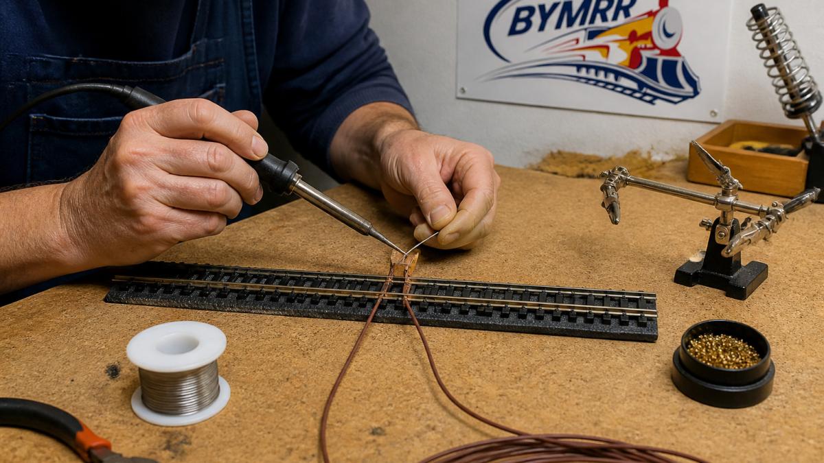
Space feeders at regular intervals along longer straight runs, typically every few feet, so voltage does not drop noticeably between connections. If you are already seeing derailments on a wired layout, step-by-step troubleshooting shows how to diagnose and fix them. Place extra feeders on sidings and turnouts, where current is more likely to be interrupted. Keep feeder wires short and tuck them beneath the roadbed so they do not snag on equipment or get caught by passing trains.
!Close-up of a hobbyist’s hands soldering a feeder wire to the underside of a model train track section on a workbench
NMRA recommended practices for layout electrical wiring
The article’s feeder guidance comes down to a few concrete placement points.
| Feeder location | Recommended practice | Reason |
|---|---|---|
| Longer straight runs | Every few feet | Prevents noticeable voltage drop |
| Sidings and turnouts | Extra feeders | Current more likely to be interrupted |
| Solder point | Underside of joiner or solder point | Keeps joints off the wheel path |
| Routing | Beneath the roadbed | Avoids snagging on equipment |
Model Train Wiring for DC: Step-by-Step Setup
DC wiring is the traditional approach and the easiest to understand for beginners. Connect a DC power pack to a bus wire running the length of the layout, then run feeders from the bus to each track section. Wire each block separately so you can control trains independently.
Follow these steps for a basic DC setup:
- Run two bus wires, one red and one black, beneath the layout.
- Connect the power pack output to the bus wires.
- Solder feeders from the bus to each isolated track block.
- Test each block with a multimeter before powering the layout.
- Use a toggle or block switch to control each section.
The biggest advantage of DC is simplicity. The biggest limitation is that each block needs its own throttle control, which becomes cumbersome on larger layouts.
Model Train Wiring for DCC: What Changes and What Stays the Same
Digital Command Control, or DCC, sends a constant track signal that carries addresses for each locomotive. The track wiring itself, including bus wires, feeders, and power connections, stays largely the same as DC. What changes is the controller and the decoder installed in each locomotive.
Because DCC does not require block-by-block throttle control, you can run multiple trains on the same track independently. The trade-off is cost and complexity. You will need a DCC command station, a booster, and decoders for your locomotives. Many beginners start with DC and convert later, which is a sound approach if you keep your wiring tidy from the outset.
Model Train Reversing Loop Wiring Without Short Circuits
A reversing loop lets a train turn around and continue in the same direction, but it creates a short circuit if the wiring is wrong. The fix is to use an auto-reversing module or a double-pole, double-throw switch to flip polarity as the train enters and exits the loop.
Isolate the loop from the rest of the track with insulated rail joiners at both ends. Wire the loop through a reversing switch, then test it slowly with a short train before running heavier consists. Watch for sparks or a locomotive stalling in the loop, which signal a polarity problem.
Common Track Wiring Mistakes and How to Troubleshoot Them
Most wiring faults fall into a few categories. Dirty or oxidized rails cause intermittent power, so clean track thoroughly before blaming the wiring. A rail-cleaning method covers the steps for restoring reliable pickup. Cold solder joints look fine but fail under vibration. Missing feeders create dead sections that appear only when a train reaches them.
Troubleshoot systematically. Use your multimeter to check voltage at several points along the bus and each feeder. If a locomotive derails at a joint, check that the rails are level and the joiner is seated correctly, since poor alignment can also cause power pickup problems. Once the wiring is fixed, learn how to prevent wiring and track derailments from happening again. Our guide on cleaning model train track explains proper rail-cleaning methods that often resolve intermittent faults.
Your First Wiring Project and Where to Get Supplies from BYMRR
For your first project, wire a small oval with two power blocks. Start with a single bus, add feeders every two to three feet, and test each block before connecting the next. This small project teaches the core skills you will use on any layout.
When you are ready to buy wire, solder, track, and power packs, check the BYMRR website to see what is available. You can buy model train accessories online and find the supplies for this project in one place. Pricing depends on quantity, dates, and delivery, so check the BYMRR website for current prices before you order.
Frequently Asked Questions
How do you wire model train track for beginners?
Start by choosing a power source, either a DC power pack or a DCC command station. Connect a pair of bus wires running the length of the layout, then solder feeder wires from the bus to each track section at regular intervals. Test each section with a meter before running trains. Work in small, tested stages rather than wiring the entire layout at once, since this makes faults far easier to find and fix.
How many track feeders does a model train layout need?
A common practice is to add a feeder to every section of track and to every few feet of straight track, with closer spacing on curves and turnouts. Many modelers attach feeders roughly every 2 to 4 feet, but the right number depends on your layout size, the scale you model, and how much voltage drop you see. If a locomotive slows or stutters at the far end of a section, add another feeder there.
Where should you place feeder wires on model train track?
Solder feeders to the underside of the rail, not the top, so they stay hidden. Place them near the joiners or at the ends of each track section, and avoid positions directly under turnout frogs unless the manufacturer’s instructions say otherwise. Keep feeder wires short and tidy, and secure them with tape or clips so they do not catch on rolling stock or pull loose during operation.
What gauge wire should I use for model train track feeders?
Most beginners use 20 to 22 AWG stranded or solid copper wire for feeders, which is thin enough to solder easily and strong enough to carry the current of typical locomotives. Use a heavier gauge such as 14 or 16 AWG for the main bus wires that run the length of the layout. Choose wire with a color scheme you can track, such as red for one rail and black for the other, to keep polarity clear.
What is the difference between DC and DCC model train wiring?
DC wiring uses a variable power pack that sends voltage directly to the track, so the locomotive speed depends on the voltage level applied to the whole block. DCC wiring sends a digital signal over the track, letting you control individual locomotives independently. DC is simpler and cheaper to start with, while DCC requires a command station and decoders in each locomotive but offers far more control on a complex layout.
Why does my model train slow down or stop on the track?
The most common causes are dirty rail surfaces, loose or poorly soldered feeder connections, and voltage drop over long track runs without enough feeders. Clean the rails with a track cleaning block, check every solder joint, and add feeders where the locomotive loses power. If a problem persists, test the track section with a multimeter to see whether the fault is in the wiring, the track, or the locomotive.
How do you wire a model train track with a reversing loop?
A reversing loop lets a train change direction without a wiring crossover. The usual method uses a double-pole double-throw switch or an automatic reversing module to flip polarity as the train enters and exits the loop. Wire the loop’s entry section with an isolated gap on one rail, and make sure the switching device changes polarity at the correct moment so the locomotive never sees a short circuit.
Can you wire multiple track sections to one power supply?
Yes, you can connect several track sections to one DC power pack or one DCC booster, provided the total current draw stays within the supply’s rated limit. Use isolated gaps and separate control switches on each section if you want independent operation. Check the total amperage of your locomotives and lighting before connecting, since overloaded supplies can shut down or overheat.
Model train track wiring rewards careful planning and patient testing. Build your first oval, learn the feeder and reversing loop basics, and your layout will run reliably for years.
